The articles are notes I took on the SQL Tutorial - Full Database Course for Beginners course.
They break into four parts:
- First article will introduce what is a database, SQL, keys and walk through the installation of MySQL on Mac.
- Second article introduces the common SQL data types, basic query syntax …etc.
- In third article we will create company tables, practice how to query on data, and introduce Functions, Wildcards …etc.
- The last article we introduce ER Diagrams, a way to diagram the requirements into figures, then we learn how to transform the ER Diagrams into actual SQL table schemas.
Now, let’s get started.
TL:DR
- ER Diagrams Intro - school example
- Designing an ER Diagram from requirements - company example
- Converting ER Diagrams to schemas - company example
- Reference
ER Diagrams Intro - school example
Entity Relationship Diagrams (ER Diagrams), diagrams that help you take the business requirements and convert them into actual database schema.
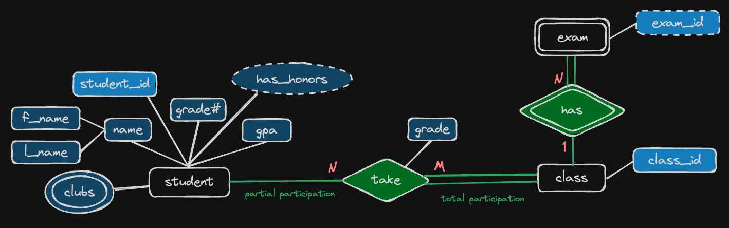
For example, let’s design a database schema for students, classes and exams information:
-
Entity - an object we want to model & store information about.
Student is an entity:

-
Attributes - specific pieces of information about an entity.
Name, grade and gpa are attributes:
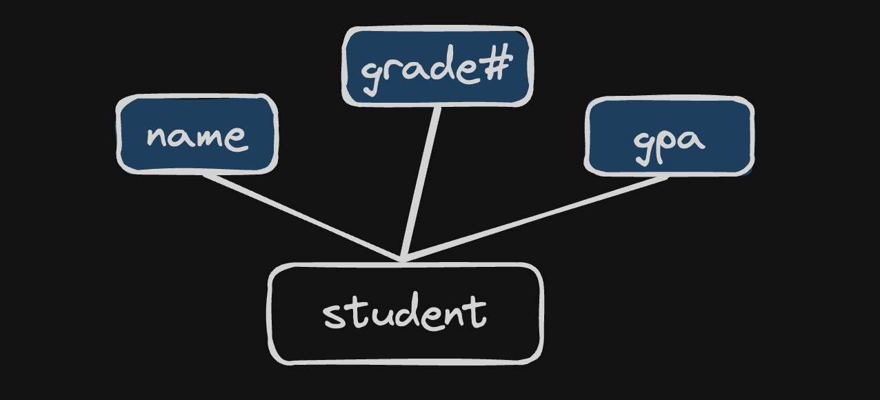
-
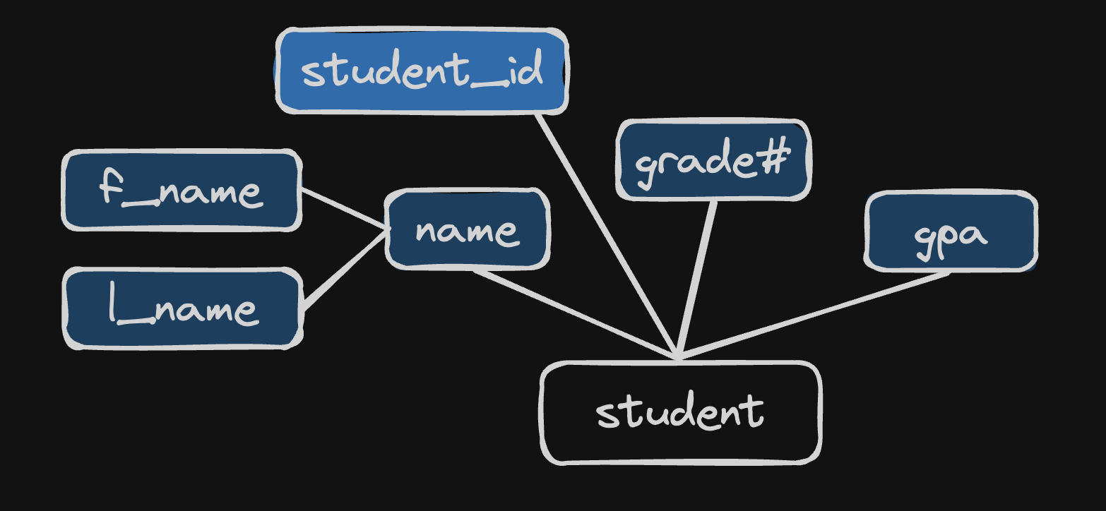
Primary Key - an attribute(s) that uniquely identify an entry in the database table.
Student ID is the primary key here, noted that we use lighter blue to identify it from other attributes:

-
Composite attribute - an attribute that can be broken up into sub-attributes.
Name can be broken up into first_name and last_name:
-
Multi-valued attribute - an attribute that can have more than one value.
For example, a student may have attend more than one club:
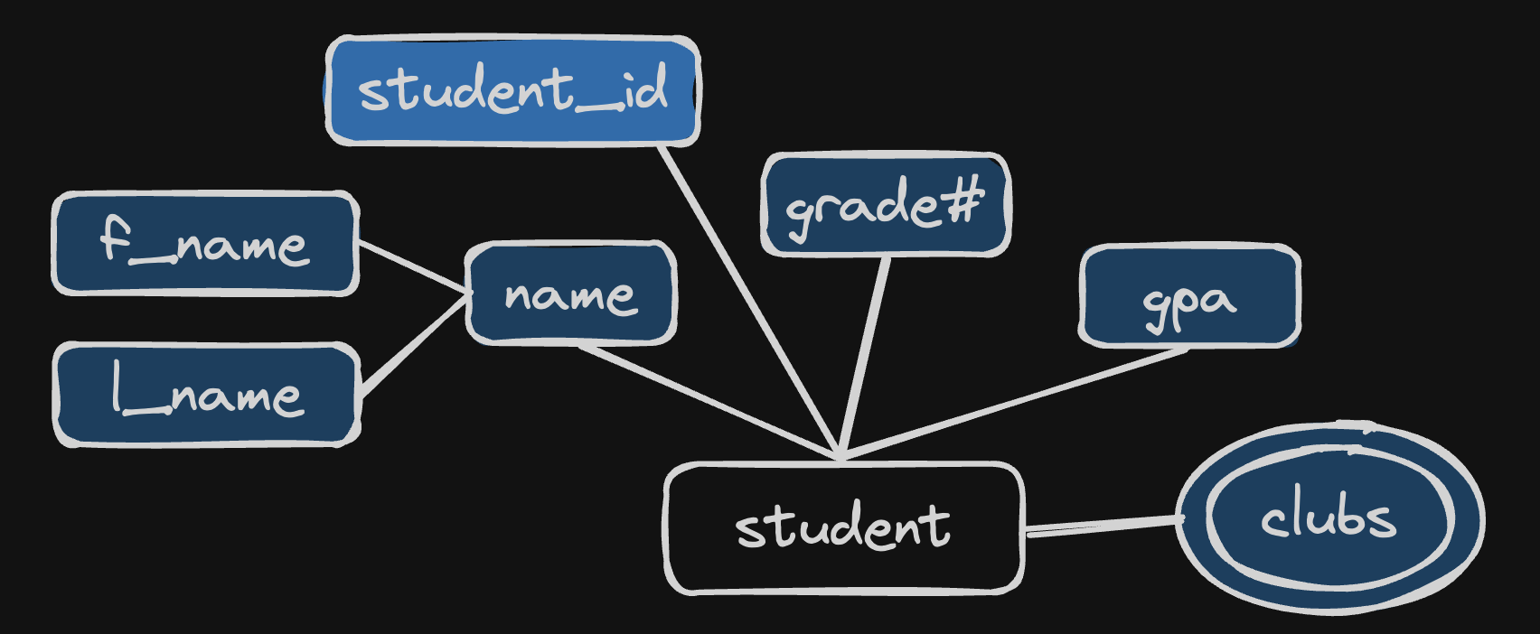
-
Derived attribute - an attribute that can be derived from the other attributes.
For example, has_honors can be derive from the gpa attribute (anyone whose gpa is higher than 3.9 will have honor …etc).
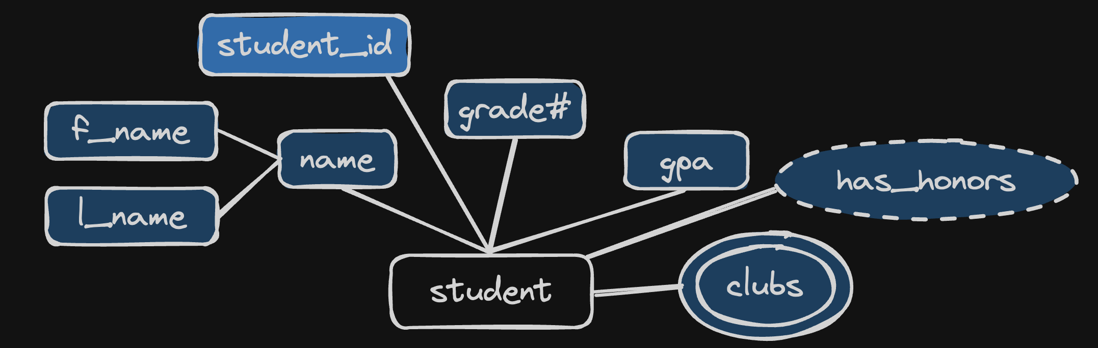
-
Multiple entities - you can define more than one entity in the diagram.
For example, besides student entity, we could also have class entity:
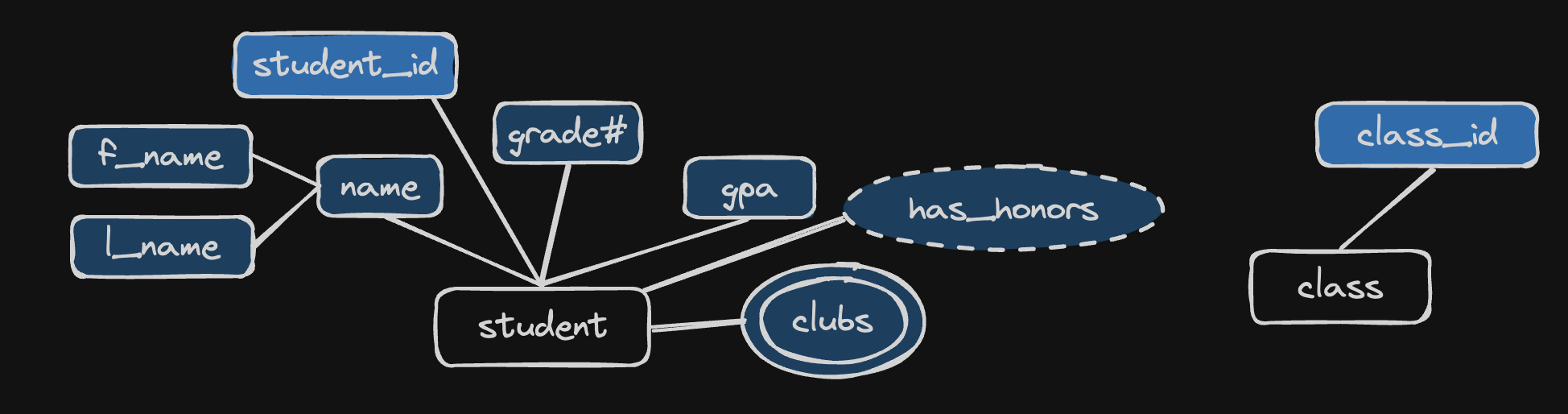
-
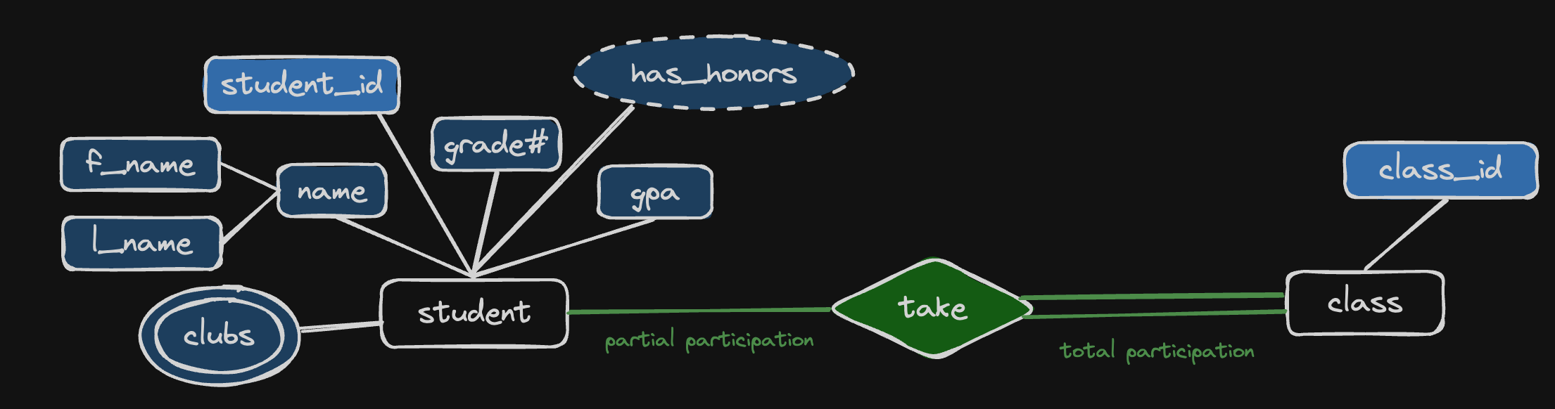
Relationships & Participation
Relationship defines a relationship between two entities;
Participation can be Partial Participation or Total Participation. Total Participation means all members must participate in the relationship.
For example, the relationship between entity student and class is the verb “take”, a student “takes” a class or a class is being “taken” by a student.
A student can decide if they want to take a class or not, and since students don’t necessarily have to take a class, this makes it a Partial Participation (single line); on the other hand, a class has to be taken by at least one student, making it a Total Participation (double lines).
-
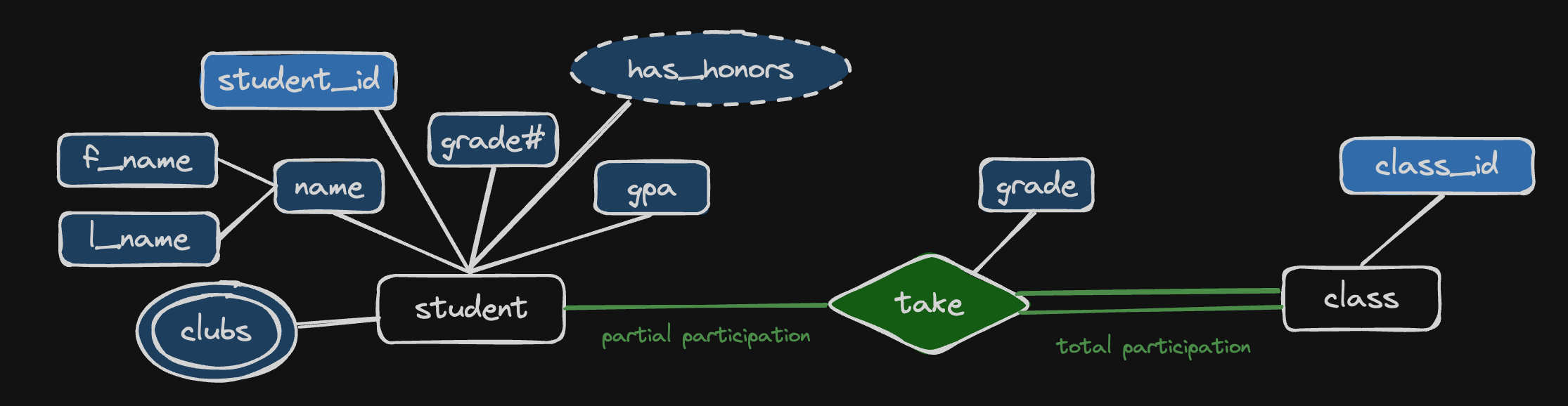
Relationship Attribute - an attribute about the relationship.
For example, a student could take a class and get a “grade” from this relation:
-
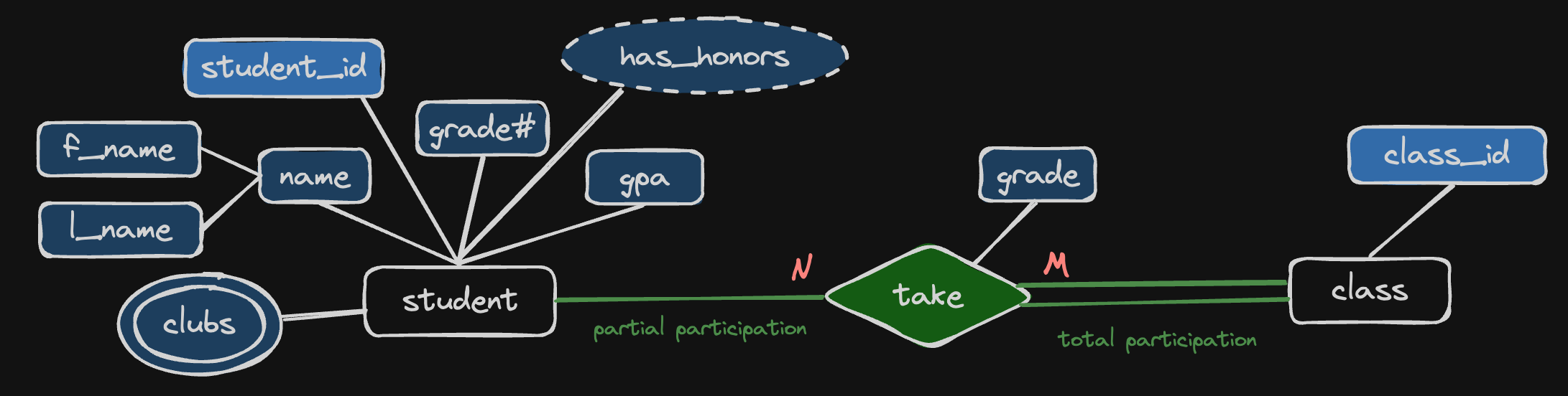
Relationship Cardinality - the number of instances of an entity from a relation that can associated with the relation.
For example, a student can take any number (M) of classes, while a class can also be taken by any number (N) of students, which makes this a N:M cardinality relationship. Other type of cardinality relationships are like: 1:1, 1:N.
-
Weak Entity & Identifying Relationship
Weak Entity is an entity that cannot be uniquely identified by its attributes alone.
Identifying Entity is a relationship that serves to uniquely identify the weak entity.
For example, an exam must be associated (has) with a class. If the class is being removed, then the exam will no longer exist.
Noted that a weak entity must have total participation in the relationship.
You may be wondering, in the class - student relationship, a class must be taken by at least one student, doesn’t that makes the class entity a weak entity? Well, I think it’s also true, so how you design this schema depends on your point of view, in my point of view, in the real world, a class must be taken by one student though, it will continue to exist even when no student has taken the class.
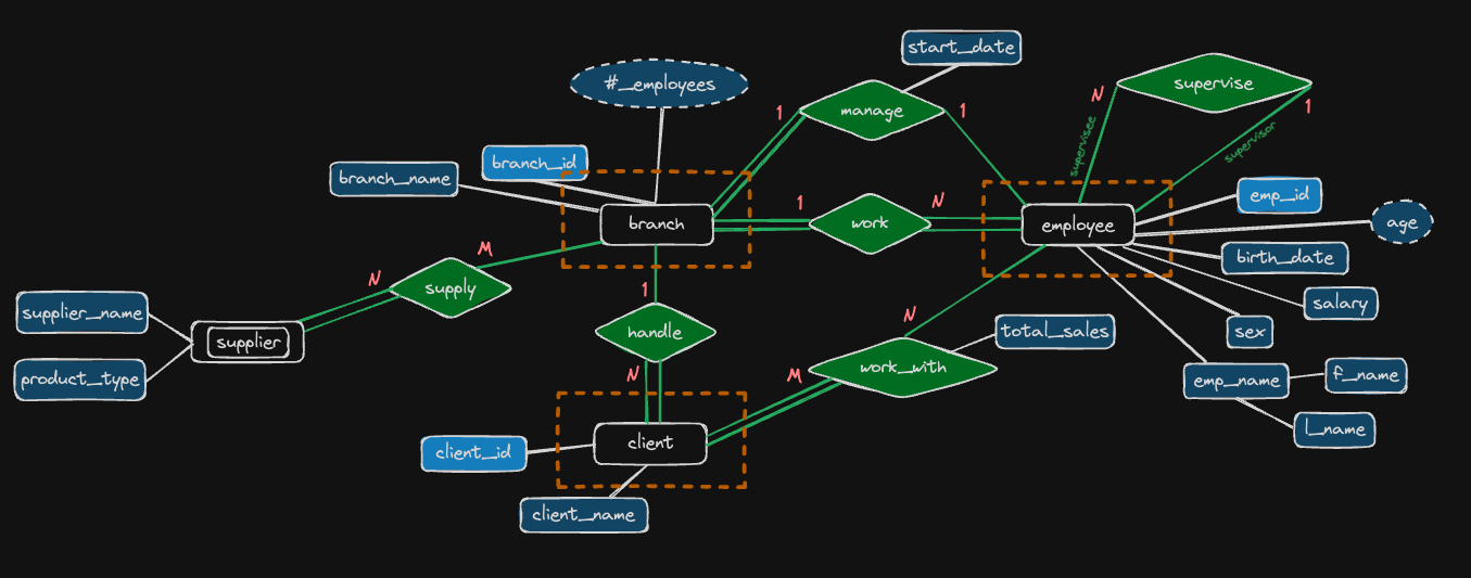
Designing an ER Diagram from requirements - company example
Let’s see the requirements written in text content first:
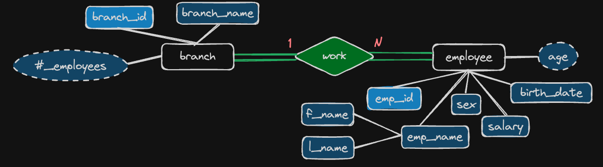
- The company is organized into branches. Each branch has a unique number, a name and a particular employee who manages it.
- The company makes it’s money by selling to clients. Each client has a name and a unique number to identify it.
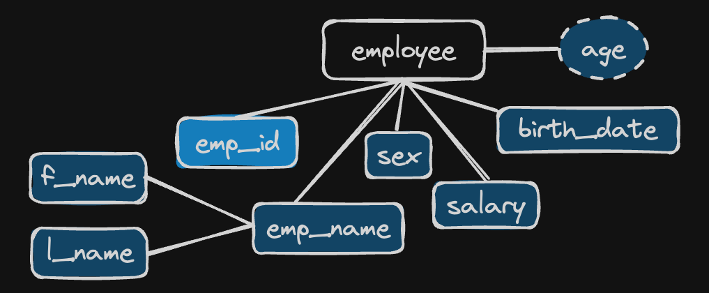
- The foundation of the company is it’s employees. Each employee has a name, birthday, sex, salary and a unique number.
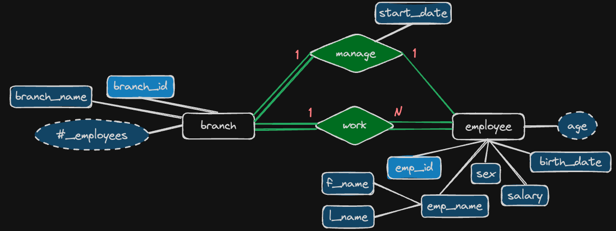
- An employee can work for one branch at a time, and each branch will be managed by one of the employees that work there. We’ll also want to keep track of when the current manager started as a manager.
- An employee can act as a supervisor for other employees at the branch, an employee may also act as the supervisor for employees at other branches. An employee can have at most one supervisor.
- A branch may handle a number of clients, with each client having a name and a unique number to identify it. A single client may only be handled by one branch at a time.
- Employees can work with clients controlled by their branch to sell them stuff. If necessary, multiple employees can work with the same client. We’ll want to keep track of how many dollars worth of stuff each employee sells to each client they work with.
- Many branches will need to work with suppliers to buy inventory. For each supplier we’ll keep track of their name and the type of product they’re selling the branch. A single supplier may supply products to multiple branches.
Now, let’s convert them into ER Diagrams.
-
The company is organized into branches. Each branch has a unique number, a name:

-
The company makes it’s money by selling to clients. Each client has a name and a unique number to identify it:

-
The foundation of the company is it’s employees. Each employee has a name, birthday, sex, salary and a unique number:
-
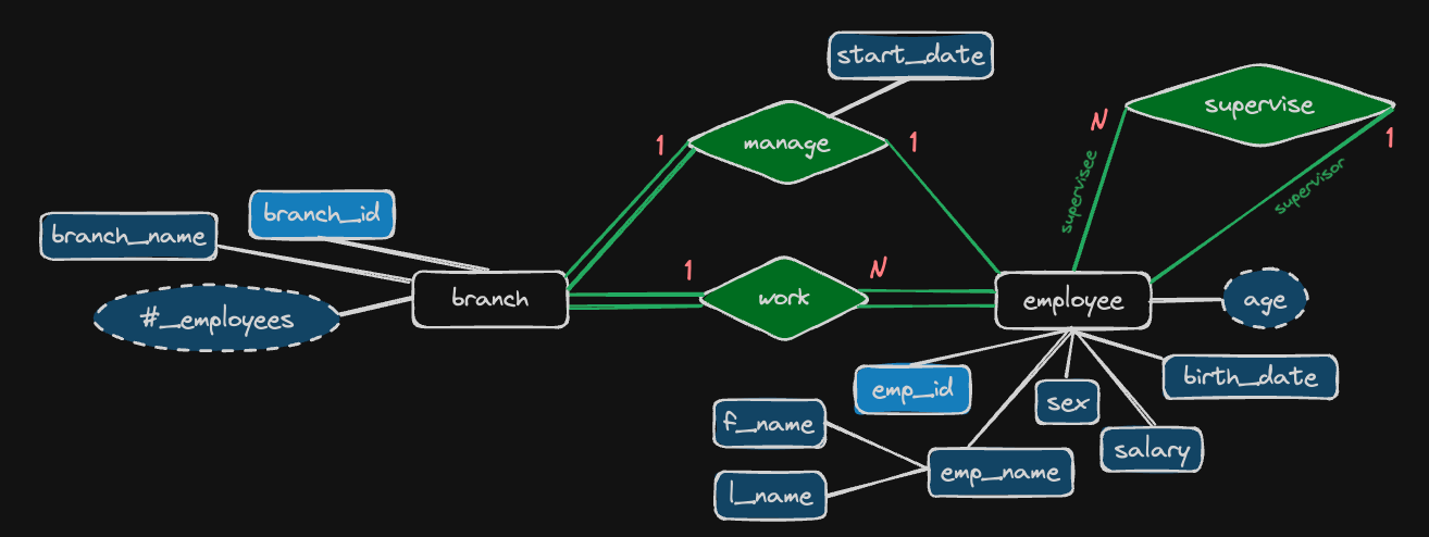
An employee can work for one branch at a time:
-
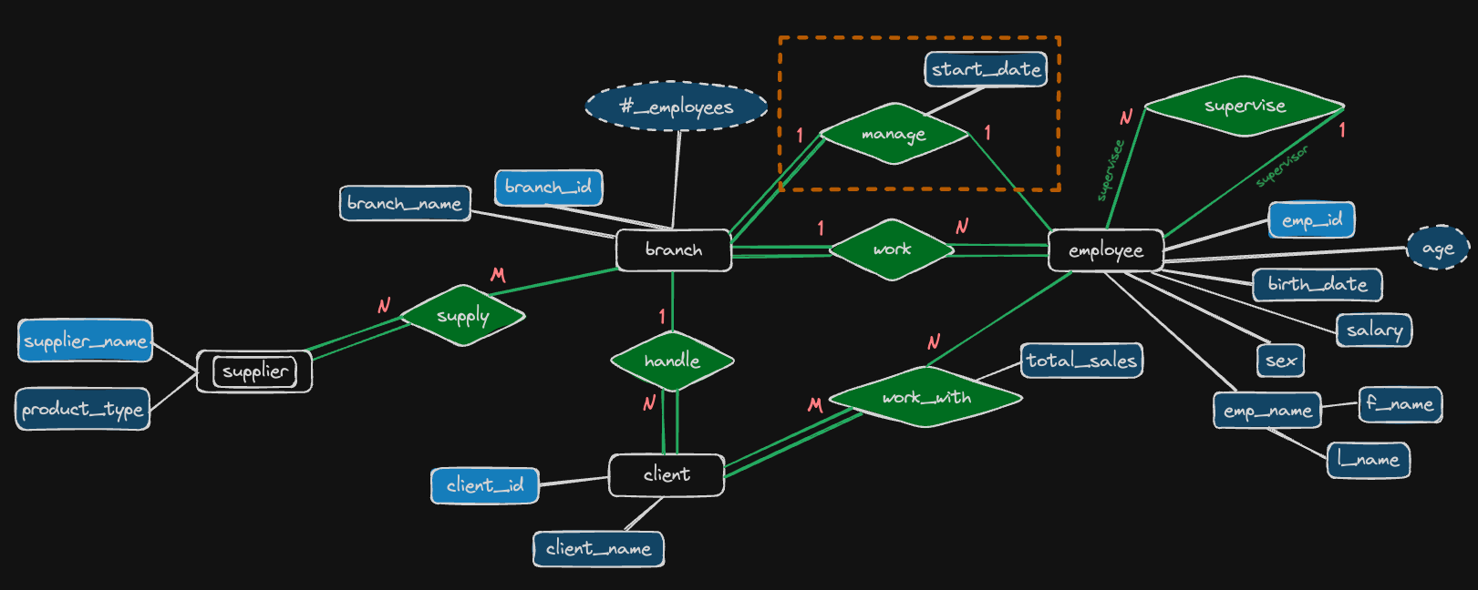
and each branch will be managed by one of the employees that work there. We’ll also want to keep track of when the current manager started as a manager:
-
An employee can act as a supervisor for other employees at the branch, an employee may also act as the supervisor for employees at other branches. An employee can have at most one supervisor:
-
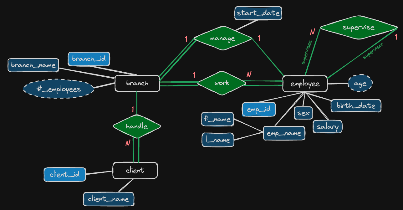
A branch may handle a number of clients, with each client having a name and a unique number to identify it. A single client may only be handled by one branch at a time.
-
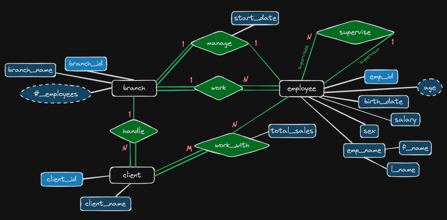
Employees can work with clients controlled by their branch to sell them stuff. If necessary, multiple employees can work with the same client. We’ll want to keep track of how many dollars worth of stuff each employee sells to each client they work with.
-
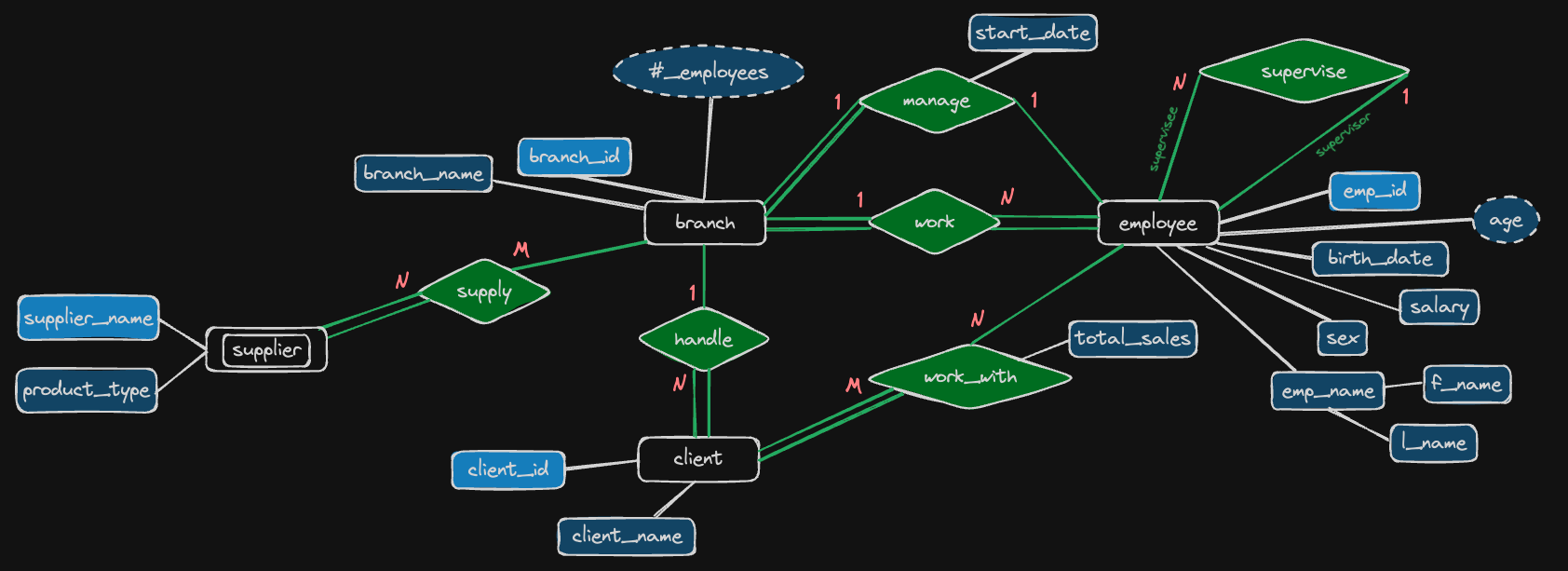
Many branches will need to work with suppliers to buy inventory. For each supplier we’ll keep track of their name and the type of product they’re selling the branch. A single supplier may supply products to multiple branches.
Converting ER Diagrams to schemas - company example
-
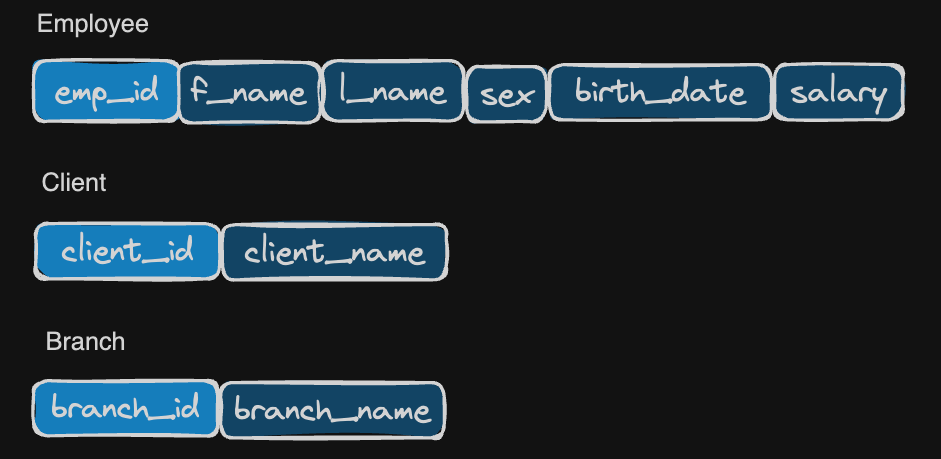
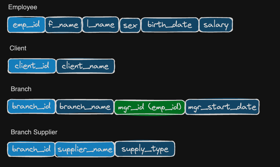
Mapping of Regular Entity Types
For each regular entity type, create a relation table that includes all the simple attributes of the entity:
-
Mapping of Weak Entity Types
For each weak entity type, create a relation table that includes all simple attributes of the weak entity.
The primary key of the weak entity table should be partial key of the entity itself and the primary key of its owner:
-
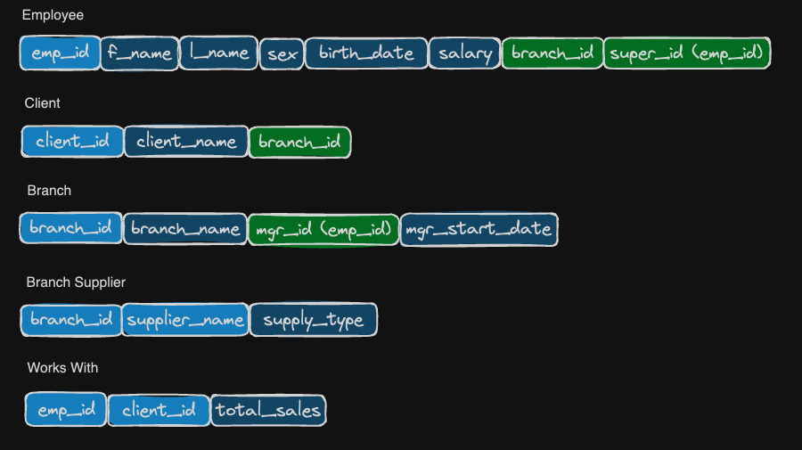
Mapping of Binary 1:1 relationship types
Include one side of the relationship as a foreign key in the other in favor of total participation. For example, branch must be managed (total participation) by one of the employees, so include the primary key of the employee table as a foreign key of the branch table plus the relational attributes:
-
Mapping of Binary 1:N relationship types
Include the “1” side’s primary key as a foreign key on the “N” side table. For example, If an employee can only work for “1” branch at a time, include the branch table’s primary key into the employee table as one of its foreign keys:


-
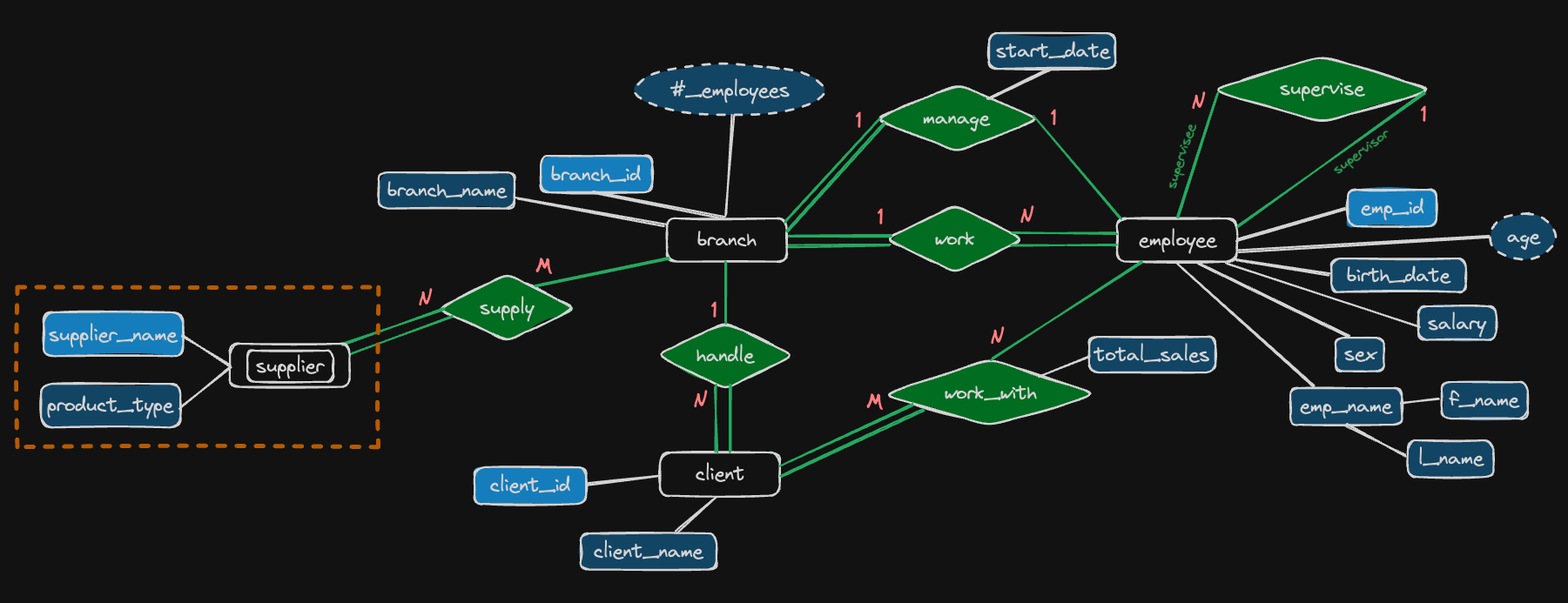
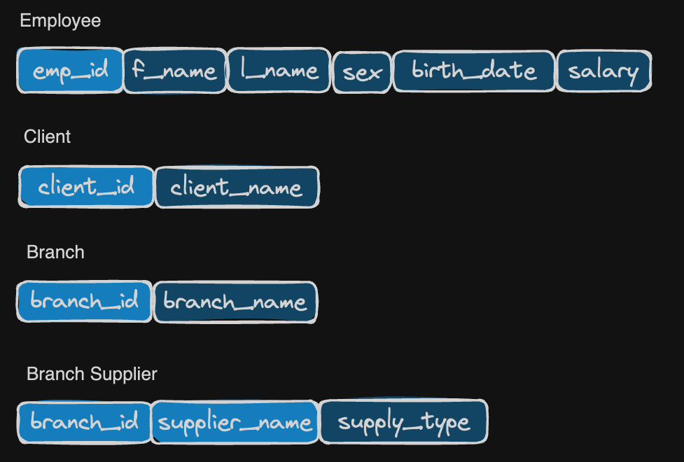
Mapping of Binary M:N relationship types
Create a new relation table who’s primary key is a combination of both regular entities’ primary keys. Also include any relationship attributes:
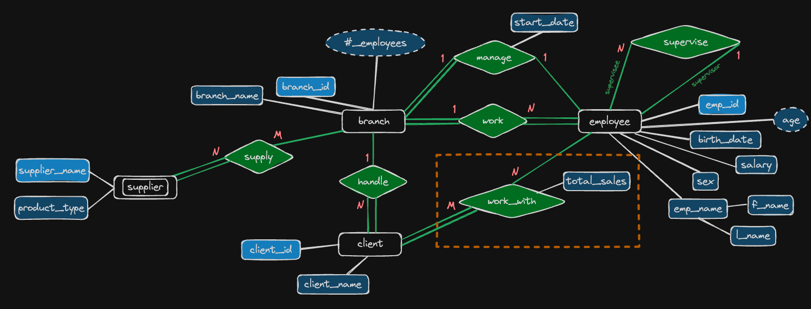
!
-
Appendix: draw connection line of primary keys and foreign keys
To be more specific, you may draw lines to indicate where the foreign keys’ come from:
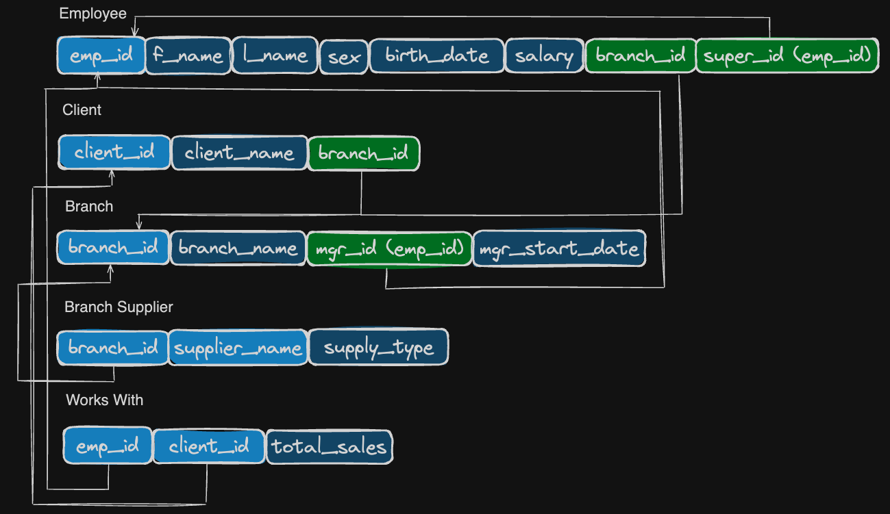
-
Wrap up
Now we have done designing a database from reading requirements to ER Diagrams to the actual tables’ schemas, the rest of the steps will be creating tables and inserting datas into them, then you can start querying the tables.
That’s it, hope you enjoy these articles (note).
Reference
- SQL Tutorial - Full Database Course for Beginners